This product is not available for new orders.
| Services Available | |
|---|---|
| Repair | No |
| Calibration | No |
| Free Support | Yes |
概览
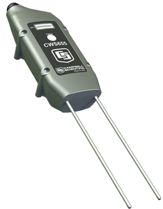
CWS655是我们的CS655土壤含水量TDR时域反射计的无线版本。它的探针长12 cm,监测土壤体积含水量、容积电导率和温度。内置的900-MHz射频电台将数据传送到CWB100无线基站或者另外一个无线传感器。900-MHz频段通常用于美国和加拿大。
优势与特点
- 多功能的传感器 — 可测量介电常数、容积电导率(EC)和土壤温度
- 对土壤质地和电导率的影响进行测量修正
- 内部跳频的射频电台提供了更长的通讯距离和更少的干扰
- 由电池供电
- 可靠的低维护性的低功耗的测量实施方案,可用在接线传感器不适用,或者不期望使用接线传感器的应用中
- 传输可路由经过多达3个别的无线传感器
- 兼容CR800、CR850、CR1000和CR3000数据采集器
图像

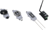
相似产品
技术说明
CWS655插入土壤的探针长12 cm,测量传播时间、信号衰减和温度;继而由这些原始数据计算出介电常数、体积含水量和容积电导率。
测量的信号衰减是用于反射检测的损失效应及传播时间的修正。损失效应修正可以让探头在容积电导率 ≤8 dS m-1 的土壤中,测量出高精度的体积含水量,并不需要实施特定的土壤校准。
由衰减测量还可以计算得到土壤容积电导率。靠近环氧树脂表面的与探针保持热接触的热敏电阻用来测量温度。如果传感器水平安装,可以得到与土壤含水量测量相同深度的精确温度测量。如果以其它的方位安装传感器,那么温度测量只能代表环氧树脂附近探针的区域。
为什么选择无线?
在那些使用有线传感器会产生一些问题的站点,继续使用有线方式会有一些问题。首先,为了保护线缆,需要穿管、挖沟,既费时又费力,有些时候甚至没有可能性。当地的防火规范可能会禁止建筑内部使用某些类型的线缆。在某些应用中,测量需要通过较长距离实现,而较长的线缆可能会降低测量质量,或者成本太高。还有些时候,增加测量的数目非常重要,而数据采集器又没有留有足够的通道用于接入额外的传感器线缆。
产品规格
| Weather Resistance | IP67 rating for sensor and battery pack (Battery pack must be properly installed. Each sensor is leak tested.) |
| 操作温度范围 | -25° to +50°C |
| Operating Relative Humidity Range | 0 to 100% |
| Power Source | 2 AA batteries with a battery life of 1 year assuming sensor samples taken every 10 minutes. (Optional solar charging available.) |
| Average Current Drain | 300 μA (with 15-minute polling) |
| Rod Diameter | 3.2 mm (0.13 in.) |
| Rod Length | 12 cm (4.7 in.) |
| Weight | 216 g (7.6 oz) |
Measurement Accuracies |
|
| Volumetric Water Content | ±3% VWC typical in mineral soils that have solution electrical conductivity ≤ 10 dS/m. Uses Topps Equation (m3/m3). |
| Relative Dielectric Permittivity |
|
| Bulk Electrical Conductivity | ±(5% of reading + 0.05 dS/m) |
| Soil Temperature | ±0.5°C |
Internal 25 mW FHSS Radio |
|
| Frequency | 902 to 918 MHz |
| Where Used | US and Canada |
| FHSS Channel | 50 |
| Transmitter Power Output | 25 mW (+14 dBm) |
| Receiver Sensitivity | -110 dBm (0.1% frame error rate) |
| Standby Typical Current Drain | 3 μA |
| Receive Typical Current Drain | 18 mA (full run) |
| Transmit Typical Current Drain | 45 mA |
| Average Operating Current | 15 μA (with 1-second access time) |
| Quality of Service Management | RSSI |
| Additional Features | GFSK modulation, data interleaving, forward error correction, data scrambling, RSSI reporting |
兼容性
Please note: The following shows notable compatibility information. It is not a comprehensive list of all compatible products.


下载
Wireless Sensor Planner v.1.7 (30.5 MB) 08-08-2013
The Wireless Sensor Planner is a tool for use with Campbell Scientific wireless sensors. It assists in designing and configuring wireless sensor networks.
常见问题解答
CWS655: 34
展开全部收起全部
-
There is not an easy way to correct CWS655 readings for temperature. The CWS655 temperature sensor is located inside the sensor’s epoxy head next to one of the sensor rods. The stainless-steel rods are not thermally conductive, causing the reported soil temperature reading to be the temperature of the sensor head near the soil surface. Because the sensor is installed vertically with the sensor head above ground, the soil temperature reading is not representative of the temperature over the length of the 12 cm rods, but the reading is closer to the temperature of the soil surface. Performing a temperature correction requires a separate temperature sensor to be buried at approximately 6 cm deep and combines that data with the values reported by the CWS655.
-
No. The equation used to determine volumetric water content in the firmware for the CWS655 is the Topp et al. (1980) equation, which works for a wide range of mineral soils but not for organic soils. In organic soils, the standard equations in the firmware will overestimate water content.
When using a CWS655 in organic soil, it is best to perform a soil-specific calibration. For details on performing a soil-specific calibration, refer to “The Water Content Reflectometer Method for Measuring Volumetric Water Content” section in the CS650/CS655 manual. A linear or quadratic equation that relates period average to volumetric water content will work well.
-
The CWS655 can detect water as far away as 10 cm in saturated sand. As the soil dries down, that distance decreases to approximately 4 cm in dry sand.
-
No. The principle that makes the CWS655 work is that liquid water has a dielectric permittivity of close to 80, while soil solid particles have a dielectric permittivity of approximately 3 to 6. When liquid water freezes, its dielectric permittivity drops to 3.8, essentially making it look like soil particles to the CWS655. A CWS655 installed in soil that freezes would show a rapid decline in its volumetric water content reading with corresponding temperature readings that are below 0°C. As the soil freezes down below the measurement range of the sensor, the water content values would stop changing and remain steady for as long as the soil remains frozen.
-
No. It is not possible to disable the logical tests in the firmware. If soil conditions cause frequent NAN values, it may be possible to perform a soil-specific calibration that will provide good results.
If permittivity is reported but the volumetric water content value is NAN, Campbell Scientific recommends a soil-specific calibration that converts permittivity to water content. This will take advantage of the bulk electrical conductivity correction that occurs in the firmware.
If both permittivity and volumetric water content have NAN values, it may be possible to perform a calibration that converts period average directly to volumetric water content.
For details on performing a soil-specific calibration, refer to “The Water Content Reflectometer Method for Measuring Volumetric Water Content” section in the CS650/CS655 manual. After a soil-specific equation is determined, it may be programmed into the data logger program or used in a spreadsheet to calculate the soil water content.
-
The volumetric water content reading is the average water content over the length of the sensor’s rods.
-
The CWS655 works best when the rods are inserted into the soil as parallel to each other as possible. To make parallel pilot holes before installation, use the CS650G Rod Insertion Guide Tool. Minor deflection of a rod during insertion, such as when it contacts a small stone or root, may not affect the readings significantly. Major deflections, however, may cause the CWS655 to operate outside of published accuracy specifications, as well as to damage the sensor housing.
-
Yes, but the pots would have to be large. The CWS655 can detect water as far away as 10 cm (4 in.) from the rods. If the pot has a diameter smaller than 20 cm (8 in.), the CS655 could potentially detect the air around the pot, which would underestimate the water content. In addition, potting soil is typically high in organic matter and clay, causing the probably need for a soil-specific calibration.
-
Period average and electrical conductivity readings were taken with several CWS655 probes in solutions of varying permittivity and varying electrical conductivity at constant temperature. Coefficients were determined for a best fit of the data. The equation is of the form
Ka(σ,τ) = C0*σ3*τ2 + C1*σ2*τ2 + C2*σ*τ2 + C3*τ2 + C4*σ3*τ + C5*σ2*τ + C6*σ*τ + C7*τ + C8*σ3 + C9*σ2 + C10*σ + C11
where Ka is apparent dielectric permittivity, σ is bulk electrical conductivity (dS/m), τ is period average (μS), and C1 to C11 are constants.
-
The equation used to determine volumetric water content in the firmware for the CWS655 is the Topp et al. (1980) equation, which works for a wide range of mineral soils but not necessarily for artificial soils that typically have high organic matter content and high clay content. In this type of soil, the standard equations in the firmware will overestimate water content.
When using a CWS655 in artificial soil, it is best to perform a soil-specific calibration. For details on performing a soil-specific calibration, refer to “The Water Content Reflectometer Method for Measuring Volumetric Water Content” section in the CS650/CS655 manual. A linear or quadratic equation that relates period average to volumetric water content will work well.