
概览
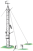
UT20 为结实耐用且重量轻的设备安装直立塔,可用于多种应用。UT20可为多种气象监测应用提供稳固的支撑点 —— 特别是火险气象站。可提供6米的标准测量高度给风传感器,也可安装天线、太阳能板、防护机箱、防辐射罩以及横臂。UT20是功能多样的设备固定件。很多用于我们的三脚塔或其它直立塔的传感器固定件,也可以用于UT20直立塔。
优势与特点
- Sturdy, long-term instrument mount
- Corrosion-resistant
图像


相似产品


技术说明
The UT20 tower includes two 3-m (10 ft) sections, one extendable mast, and two cable-tie kits. It has a 1.5-m (5 ft) length and a 3.175-cm (1.25 in.) outer diameter [swagged to 2.5 cm (1 in.) OD]. The 3-m sections are constructed from 2.5-cm (1 in.) OD aluminum tubing.
Top 3 m Section
This section's width is 33.3 cm (13.1 in) on a side (center of tubing to center of tubing).
Bottom 3 m Section
This section's width is 43.2 cm (17 in) on a side (center of tubing to center of tubing).
Mounting Base, Grounding Kit, and Guying Kit
This tower requires a mounting base and grounding kit. Campbell Scientific also recommends guying the UT20 with our UTGUY Guy Kit. See Ordering Info on web page for more information.
产品规格
| Material | Hardened drawn 6063-T832 aluminum |
| Guyed Tower Area Requirements | ~3.5 m (11.5 ft) radius |
| Required Concrete Pad Dimensions |
91 x 91 x 122 cm (36 x 36 x 48 in.) for B18 Concrete Mounting Base Concrete pad requirements assume heavy soil; light, shifting, or sandy soils require a larger concrete pad. |
| Extendable Mast |
|
| Pipe Outer Diameter |
|
| Crossarm Measurement Height | 6 m (20 ft) |
| Height | 6.1 m (20 ft) |
| Shipping Dimensions | 310 x 46 x 46 cm (122 x 18 x 18 in.) |
| Shipping Weight | 23 kg (50 lb) |
Maximum Wind Load Recommendation |
|
| B18 Base (unguyed) | 177 km/h (110 mph) |
| RFM18 Base (with UTGUY) | 177 km/h (110 mph) |
| UTBASE (unguyed) | 177 km/h (110 mph) |
| -NOTE- |
Wind load endurance is affected by quality of anchoring and installation; guy wire tension; soil type; guy angle; and number, type, and location of instruments fastened to the tower. Wind load recommendation assumes proper installation, proper anchoring, adequate soil, and total instrument projected area of less than 0.19 m2 (2 ft2) at the height of the tower. For the RFM18 base, the wind load recommendation also assumes that the UTGUY’s turnbuckles are preloaded just enough to equalize tension and that the tower is guyed at a 60 degree angle relative to the ground (maximum). |
兼容性
Please note: The following shows notable compatibility information. It is not a comprehensive list of all compatible products.
固定设备
| Product | Compatible | Note |
|---|---|---|
| 019ALU (retired) | ||
| CM202 | ||
| CM202SS | ||
| CM203 | ||
| CM204 | ||
| CM204SS | ||
| CM206 | ||
| UT018-5 (retired) |
Additional Compatibility Information
Enclosure Brackets
The “-TM” mount option for our environmental enclosures is used to attach our enclosures to a UT20 tower. An enclosure ordered with the “-TM” option will be shipped with a three-piece bracket mounted to the top of the enclosure and an identical three-piece bracket mounted to the bottom of the enclosure. This mounting bracket option uses the same three-piece brackets as the "-MM" option, except the pieces are rearranged so that the flanges are on the side of the bracket instead of in the middle. The distance between the centers of each flange needs to be 17”.
Note:
Enclosures with the "-TM" option are shipped configured for the UT10 tower. UT20 customers will need to: (1) remove the bolts attaching the bracket to the enclosure, (2) slide out the flange sections so that the distance between the center of each flange is 17", and (3) reattach the bracket to the enclosure using the original bolts.
相关技术文档


常见问题解答
10760: 1
-
In applications involving a tower and either strong winds or the need to attach a lot of gear to a crossarm, Campbell Scientific recommends using a longer crossarm with a second CM210 Crossarm-to-Pole Bracket. (One CM210 ships with each CM202, C204, or CM206 crossarm.) Secure the crossarm to two points on the tower to add stability and rigidity to the crossarm. The crossarm can be shifted in a foot (the distance between the vertical supports on the tower), or the crossarm can be centered on the tower.