This product is not available for new orders.
| Services Available |
|---|
概览
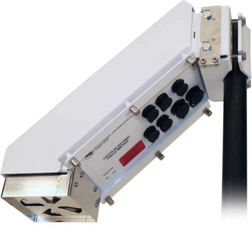
CS110用于雷电预警应用,或测量局部电场的研究应用。CS110测量地表的大气电场强度的垂直分量,CS110是电场系统的一部分,它含有一体式的CR1000数据采集器,因而也可扩展额外的其它传感器和外设。
备注: CS110 电场系统请参考 LW110 Lightning Warning System page.
视频承蒙KSL.com提供
优势与特点
- 低功耗
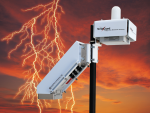
- 感应潜在的闪电威胁,在闪电发生之前提供预警
- 易于维护 — 定子容易移除进行清洁
- 关于每一个测量的广泛的自检验诊断信息,减少或消除了定期的维护
- 结实的构造
- SG000 Strike Guard可与我们的CS110电场计配合使用,创建完整的闪电威胁测量和分析系统
图像

3D/CAD 文件:
技术说明
CS110使用往复快门,而不是传统的旋转叶片式电场阻断。往复式快门通过方便的不锈钢带连接到地电位。不锈钢带在其疲劳限值以下操作,产生了极为可靠的与快门的地电位连接。
往复式方法比传统方法能提供更好的低频噪声性能,因为它有一个便利的零电场(快门关闭)参考,零电场参考可以使得CS110测量并继而修正每次测量的电子漂移电压、接触电位、泄漏电流(正在申请专利)。
CS110还含有测量和补偿发生在充电放大输入上的绝缘层泄漏电流的电路,消除了由错误绝缘引起的测量误差。如果由于污染导致绝缘层表面变得导电,那么泄漏电流补偿电路会产生一个等量的反极性电流给充电放大输入,防止了电子的饱和。
质保
CS110对产品材料和工艺的缺陷提供1年质保。Campbell Scientific不保证CS110一定符合客户的要求,或者CS110的操作一定不间断或无错误。
大气或当地的电场条件或者不同的站点特征,可能会导致错误的信息、晚报的数据,或者是不完整或不准确的数据。CS110只测量很可能发生雷电的条件。就象天气预报那样,CS110的测量只是帮助评估雷电的可能性。在CS110没有警报时,雷电也可能会导致人身伤害甚至死亡或财产损失。
Campbell Scientific对CS110使用、失败或失灵,引起的特别的、间接的、或随之而来的损失,没有责任。关于CS110质保的完整声明在CS110的说明书中。
产品规格
| -NOTE- | An embedded CR1000M datalogger module (ordered as pn 18292) is required for every CS110 purchased; see Common Accessories section on Ordering Information page. |
| CE Compliance Standards to which Conformity Is Declared | BS EN61326:2002 |
| Lightning Protection | Multi-stage transient protection on all external interfaces |
| Power Requirements | 11 to 16 Vdc |
| Baud Rates | Selectable from 300 to 115.2k bps |
| ASCII Protocol | One start bit, one stop bit, eight data bits, no parity |
| 操作温度范围 |
|
| Operating Relative Humidity | 0 to 100% RH |
| Mounting | Vertical pipe with outer diameter of 1.91 to 6.35 cm (0.75 to 2.5 in.) |
| Communication Ports |
|
| Dimensions | 15.2 x 15.2 x 43.2 cm (6 x 6 x 17 in.) |
| Weight | 4 kg (9 lb) |
Current Drain |
|
| Peak Current Demand | 750 mA (occurs during motor operation) |
| Average |
|
Accuracy |
|
| -NOTE- | Refer to the sensor manual for resolution, sensitivity, and noise specifications. |
| Parallel-Plate Configuration | ±1% of reading + 60 V m-1 offset |
| 2 m CM110 Tripod Configuration | ±5% of reading + 8 V m-1 offset |
兼容性
| IMPORTANT! An embedded CR1000M datalogger module (ordered as p/n 18292) is required for every CS110 purchased; see Common Accessories in ordering information. Generally, the CS110 should be run with the latest released CR1000 operating system (OS) available via "Support" on this website. However, CR1000 OS version 27.05 should NOT be downloaded to standard CS110s. OS version 27.05 was built to accommodate the ~40,000 v/m efields measured on ocean buoys. The special OS also requires a capacitor change on the CS110 panel board. The CS110 should not be run with OS 28 (CR1000.Std.28.obj). A bug in OS 28 prevents changing the setup "Constants" via the keyboard or the terminal emulator. |
Data Logger Considerations
The internal CR1000M (required) can be interfaced to another data logger via the Power/SDM cable if the application requires an additional data logger.
Programming
The CR1000’s on-board programming language, CRBasic, provides data processing and analysis routines that support user control over sample (measurement) rates and setting of alarm conditions. LoggerNet Datalogger Support Software facilitates programming, communications, and data retrieval between the CS110 and a PC.
Using the CS110 as a Weather Station
The CS110 has sealed connectors for attaching meteorological sensors and three digital control ports for controlling external devices and/or triggering alarms. The embedded CR1000 datalogger measures the sensors, processes the measurements, stores the data in tables, and can initiate communications.
Compatible Sensors
| Connector Label | Compatible Sensors (one sensor per connector) |
| Temp/RH | HMP60-L4-C Vaisala Temperature and RH Probe (RH sensing element is field replaceable.) |
| Wind | 05103-L4-C RM Young Wind Speed/Direction |
| Solar | CS305-ET Apogee Pyranometer, CS100 Setra 278 Barometer (barometer connects to the CS110 via the 17460 cable; barometer is typically housed in the LW110 enclosure), GPS16X-HVS Garmin GPS Sensor |
| Rain | TE525-L25-C Texas Electronics rain gage or TB4-L25-C HS Hyquest Solutions rain gage |
Compatible Communication Devices
Communication options compatible with the embedded CR1000 include direct connect, Ethernet, phone modems (land-line and cellular), radios, short haul modems, GOES satellite transmitters, and multidrop modems.
Zero Electric Field Cover
The 17642 Zero Electric Field Cover (ordered separately) is used to check the electric field offset voltage of the CS110. If the measured electric field is ≥|60 V/m| with the Zero Electric Field Cover on, then inspection and cleaning of the electrode surfaces is recommended.
SG000 Strike Guard Lightning Sensor
The SG000 (ordered separately) can be used in conjunction with our CS110 to create a complete lightning-threat measurement and analysis system. This system combines the advantages of two complementary lightning-warning technologies. The SG000 reports actual lightning strikes occurring at distances up to 20 miles—providing a comfortable warning time for incoming storms. The CS110 reports electric fields associated with local thunderstorm development—providing a warning prior to lightning strikes.
下载
CS110 Example programs v.1 (3 kB) 05-05-2020
A CS110 weather station program and a CS110 transfer standard site calibration program. The weather station program measures electric field, rainfall, wind speed and direction, solar radiation, relative humidity, air temperature. The calibration program measures panel temperature, battery, internal relative humidity, and electric field.
常见问题解答
CS110: 6
展开全部收起全部
-
When programmed as a “Slow Antenna” sampling at 100 Hz, the CS110 would provide polarity information but not actual current flow in the wire; therefore, Campbell Scientific does not recommend using a CS110 for this purpose.
-
The following information can help determine the effective range (spatial range) of the CS110:
- Thousands of miles: When there are no clouds in the sky, the CS110 responds to what is called the fair weather electric field created by the “global electric circuit.” Thunderstorms worldwide transfer charge to the upper atmosphere, which comes down worldwide as an electric field that varies from roughly -100 to -200 v/m on flatland sites. Our customers have indicated that the fair weather electric field is enhanced by high terrain. Interestingly, there are daily and seasonal changes to this global electric circuit.
- 20 miles: Lightning strikes in thunderstorms as far as 20 miles away are discernable in the fair weather electric field from a flatland site. The strikes show up as sharp changes in the electric field followed by a more gradual recovery. It is unknown if the distance is greater on a high ridgeline.
- 5 to 7 miles: When charged clouds are within five to seven miles, they can positively or negatively change the electric field above or below the fair weather electric field. Even when the actively producing cloud-to-ground lightning portion of the storm is 20 miles away, an anvil cloud from that storm that comes within five to seven miles of the CS110 will change the electric field measured by the CS110. Think of clouds attached to an active thunderstorm as electrical conductors. Even anvil clouds that were once part of a thunderstorm that has since dissipated will hold their charge for a significant period.
- A mountain between a charged cloud and the CS110 will block the electric field influence that the cloud would have had on the CS110.
For more information on this topic, refer to the “Cumulonimbus” section (section 3.2) of the book Lightning: Physics and Effects by Vladimir A. Rakov and Martin A. Uman.
-
The CS110 and the tower should be positioned away from each other a distance of three times the tower’s height.
If the radio signal is strong enough, the SG000 may pick it up as one of the two components the SG000 measures to detect lightning. If this signal coincides with a light flash from a windshield or headlight, it could generate a false strike signal. Also, constant bombardment of the SG000 by sufficiently strong RF signals will pull the sensor out of its quiescent state, affecting its current drain. This will eventually degrade the battery and shorten its expected four-year lifespan.
-
The CS110 uses the same gas discharge tubes, etc., so it provides similar surge protection as the CR1000. The ground paths are different, although both are intended to provide a good ground path through the ground lug on the wiring panel and the case ground hardware on the CS110.
-
The FC100 is required to communicate with the SG000 Strike Guard Lightning Sensor. The SG000 is an option for the CS110 Electric Field Sensor and the LW110 Lightning Warning System.
-
To simulate a lightning strike to the SG000, use a camera flash to flash the glass bulb from a distance of 5.08 to 7.62 cm (2 to 3 in.). Note: A flash from a cell phone usually isn't large enough to simulate a lightning strike.
To simulate high electric fields on the CS110, run a comb through your hair and hold it a distance of 2.54 to 5.98 cm (1 to 2 in.) from the shutter of the CS110. Other items such as plastic bags or balloons, or fur on glass, can be used as well.
案例研究
Overview In the heart of the UAE’s Empty Quarter desert—one of the harshest and least hospitable......阅读更多

CS110 Electric Field Meter to Recreate the Carnegie Curve of Earth's Fair-Weather Electric Potential Gradient INESC......阅读更多