
带自校准功能,适用于能量平衡涡度协方差和波文比系统


概览
HFP01SC 测量土壤热通量,通常用于能量平衡系统或波文比通量系统。倾向用于那些要求最高可能测量精度的应用。每个站点至少需要2个土壤热通量传感器,才能提供足够的空间平均。带有非均匀介质的站点可能需要更多的传感器。
优势与特点
- Corrects for errors due to differences in thermal conductivity between the sensor and surrounding medium, temperature variations, and slight sensor instabilities
- Compatible with most Campbell Scientific data loggers
- Uses Van den Bos-Hoeksma self-calibration method to provide a high degree of measurement accuracy
图像

技术说明
HFP01SC 包含一个热电堆和一个薄膜加热器。热电堆来测量通过传感器板上的温度梯度。在原位野外校准期间,加热器生成通过传感器板的热通量,其功率大小由数据采集器测量;数据采集器同时测量传感器的响应信号,再计算生成新的校准常数。出厂时,每一个热通量板传感器都会单独校准,输出热通量。
自校准修正了由传感器与周围介质之间热传导率的差异、温度变化以及轻微的传感器不稳定性等因素所导致的误差。
产品规格
| Sensor Type | Thermopile with film heater |
| Sensitivity | 50 μV W-1 m-2 (nominal) |
| Nominal Resistance | 2 Ω |
| Temperature Range | -30° to +70°C |
| Expected Typical Accuracy | ±3% of reading |
| Heater Resistance | 100 Ω (nominal) |
| Heater Voltage Input | 9 to 15 Vdc |
| Heater Voltage Output | 0 to 2 Vdc |
| Duration of Calibration | ±3 minutes @ 1.5 W (typically performed every 3 to 6 hours) |
| Average Power Consumption | 0.02 to 0.04 W |
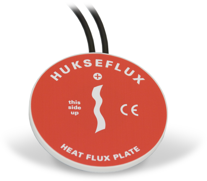
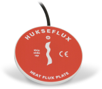
| Plate Diameter | 80 mm (3.15 in.) |
| Plate Thickness | 5 mm (0.20 in.) |
| Weight | 200 g (7.05 oz) without cable |
相关技术文档
下载
CR1000X HFP01SC Example program v.2 (3 kb) 18-02-2020
CR1000X program that measures the HFP01SC, performs the self-calibration, and checks for calibration validity. Refer to the manual for the equations used for the self-calibration and calibration-validity checks. A table in the manual provides a cross reference of the terms in the equations in the manual with the constants and variables in the example data logger program.
常见问题解答
HFP01SC-L: 9
展开全部收起全部
-
Rather than using a running average to find the millivolt output during a calibration, use a single sample with 50 or 60 Hz integration. See Example 1 in the 2014 or later version of the HFP01SC-L manual.
-
Can the HFP01SC-L be embedded in railroad ballast, which comprises a blend of coarse rock particles?
No. The HFP01SC-L must be in full contact with the media. Railroad ballast is too coarse.
-
The example CRBasic program runs in either SequentialMode or PipeLineMode. To force the CRBasic program to run in PipeLineMode, add the instruction PipeLineMode to the beginning of the program.
-
A calibration shift occurs if the HFP01SC-L is not making full contact with the soil during the calibration cycle. The following could cause the plate to lose contact with the soil: a soil freeze/thaw cycle, soil swelling/contracting because of extreme drying/wetting cycles, or rodents burrowing past the plate.
-
The in-situ calibration is helpful for quality assurance/quality control. The multiplier determined from the in-situ calibration should be within ±10% of the factory-determined calibration. If it is not, the plate may be damaged, not wired correctly to the data logger, or not making full contact with the soil.
-
The information included on a calibration sheet differs with each sensor. For some sensors, the sheet contains coefficients necessary to program a data logger. For other sensors, the calibration sheet is a pass/fail report.
-
Because of the loss of IR radiation, nearly all thermopile instruments typically have a negative offset. This offset is most easily visible at night-time, when a small negative value is read instead of zero. This same offset is present during the daytime, but it is not as visible because of the large solar signal.
Another common issue involves leveling an instrument. Leveling a thermopile instrument can cause errors in the direct beam component because the cosine response is not correct. These errors are more notable when the sun is close to the horizon because the angle is so shallow.
-
Add the appropriate code to the data logger program using a program example from the HFP01SC-L manual. Alternatively, contact Campbell Scientific for assistance.
案例研究
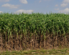
Overview In the fight against climate change, innovative solutions are emerging to address the global challenge......阅读更多
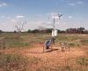
This case study discusses the integration of CPEC310 and AP200 systems to explore the theories......阅读更多
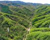
Scientists and land-use managers have long recognized the importance of forest lands for their role......阅读更多
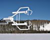
The Austin College Weather Station (ACWX) is located on Austin College's Sneed Environmental Research Area,......阅读更多