This product is not available for new orders. We recommend ordering: Granite VWire 305.

| Services Available |
|---|
概览
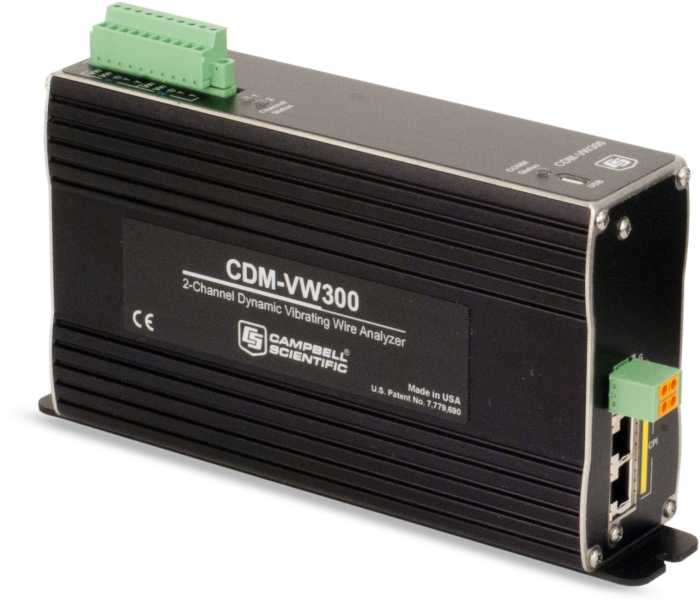
The CDM-VW300 is a two-channel interface that you can use between standard single-coil circuit vibrating wire sensors and data loggers to allow shorter intervals between measurements. With the CDM-VW300 interface, you can achieve much faster and better measurements without having to purchase new sensors. Sensors typically used with the CDM-VW300 are strain gages, load cells, pressure transducers, crackmeters, and tiltmeters.
This interface uses an excitation mechanism that maintains the vibrating wire sensor in a continuously vibrating state. The interface measures the resonant frequency of the wire between excitations using the patented vibrating wire spectral-analysis technology (VSPECT®). VSPECT® provides very fine measurement resolution and also limits the influence of external noise by discriminating between signal and noise based on frequency content. Because of this technology, the signal can be carried through longer cables, giving you flexibility in your sensor and data logger siting.
You can connect multiple CDM-VW300 modules to one data logger. The CDM-VW305 is similar to this item, but it has eight channels.
The dynamic vibrating wire measurement technique is protected under U.S. Patent No. 8,671,758, and the vibrating wire spectral-analysis technology (VSPECT®) is protected under U.S. Patent No. 7,779,690.
优势与特点
- Interfaces to standard single-coil vibrating wire sensors
- Two simultaneously sampled channels per module; synchronizable across multiple modules
- Dynamic measurement rates of 20 to 333 Hz
- Static measurement at 1 Hz made simultaneously with the dynamic measurement
- Spectral interpolation approach provides superior noise immunity and measurement resolution compared to time-domain period-averaging approach
- Excitation method provides frequent low-energy pulses to maintain a continuous resonant vibration in the sensor
- Thermistor input for each vibrating wire channel is sampled at 1 Hz
- Data logger communications via CPI
- User-configurable, onboard post-processing of the data including frequency output conversion, temperature conversion, and rainflow histogram collection
图像
技术说明
除动态振弦测量,CDM-VW300还可用于其它测量。随动态测量一同产生的每秒一次的静态振弦测量,它提供了更精细的测量分辨率和对外部噪声源的更强的抗干扰能力。CDM-VW300还包括与每个振弦通道相对应的热敏电阻输入通道,1 Hz频率时提供高达24位高精度的测量结果。最后,提供一组丰富的诊断参数与振弦数据。
CDM-VW300拥有简单的后处理数据的能力,这点通过计算内部共同值来完成。振弦数据以测量频率来显示,或者以乘数和偏移量行程方波来显示。热敏电阻的数据显示为阻抗或利用Steinhart-Hart系数转换成摄氏度来显示。CDM-VW300也可根据最终数据编译降雨流量柱状图,也可按用户指定的间隔报告数值。
产品规格
| -NOTE- | Electrical specifications are valid over a -25° to +50°C range unless otherwise specified. Non-condensing environment required. |
| Scan Rates | 20, 50, 100 Hz |
| CPI Baud Rate | Selectable from 25 kbps to 1 Mbps |
| Input Resistance | 5 kΩ |
| Excitation Voltage Range | 0 to ±3 V (6 V peak-to-peak) |
| Excitation Voltage Resolution | 26 mV |
| Operating Temperature Range |
|
| Measurement Frequency Accuracy | ±(0.005% of reading + measurement resolution) |
| Sustained Input Voltage without Damage | -0.5 to +7.1 V |
| USB | USB 2.0 full speed connection is available for attaching the device to a PC. (This port is provided to configure the module, send updates, and communicate with the Dynamic Vibrating Wire Toolbox software. The USB port is not provided for use within a permanent data collection system.) |
| CPI | Used for connection to the data logger. Baud rate selectable from 50 kbps to 1 Mbps. (Allowable cable length varies depending on baud rate, number of nodes, cable quality, and noise environment, but can be as long as 2,500 ft under proper conditions.) |
| Mounting | Standard 1-in. grid (Optional DIN rail mounting available.) |
| Warranty | One year against defects in materials and workmanship |
| Dimensions | 20.3 x 12.7 x 5.1 cm (8 x 5 x 2 in.) |
Measurement Resolution at Sample Rates |
|
| -NOTE- | Typical values for a 2.5 kHz resonant sensor |
| 1 Hz Sample Rate | 0.005 Hz RMS (noise level) |
| 20 Hz Sample Rate | 0.008 Hz RMS (noise level) |
| 50 Hz Sample Rate | 0.015 Hz RMS (noise level) |
| 100 Hz Sample Rate | 0.035 Hz RMS (noise level) |
| 200 Hz Sample Rate | 0.11 Hz RMS (noise level) |
| 333.3 Hz Sample Rate | 0.45 Hz RMS (noise level) |
Sensor Resonant Frequency Range |
|
| 20 Hz Sample Rate |
|
| 50 Hz Sample Rate |
|
| 100 Hz Sample Rate |
|
Thermistor |
|
| Completion Resistor | 4.99 kΩ 0.1% |
| Excitation Voltage | 1.5 V |
| Resolution | 0.002 Ω RMS (@ 5 kΩ thermistor resistance) |
| Accuracy | 0.15% of reading (Thermistor accuracy and resistance of the wire should be considered as additional errors.) |
| Measurement Rate | 1 Hz |
Power Requirements |
|
| Voltage | 9.6 to 32 Vdc |
| Typical Current Drain | 115 mA (@ 12 Vdc) |
兼容性
Please note: The following shows notable compatibility information. It is not a comprehensive list of all compatible products.
数据采集器
| Product | Compatible | Note |
|---|---|---|
| CR200X (retired) | ||
| CR206X (retired) | ||
| CR211X (retired) | ||
| CR216X (retired) | ||
| CR295X (retired) | ||
| CR3000 (retired) | ||
| CR6 | ||
| CR800 (retired) | ||
| CR850 (retired) | ||
| Granite 9 |
Additional Compatibility Information
Data Logger Considerations
The SC-CPI Datalogger Serial-to-CPI Interface is required to connect the CDM-VW300 to a compatible data logger (except the CR6). A 5-conductor cable connects the data logger to the SC-CPI, and an Ethernet cable connects the SC-CPI to the CDM-VW300.
Multiplexers
The CDM-VW300 is not designed to work with multiplexers.

下载
CDM-VW300 Example Programs (45.4 KB) 23-05-2013
CRBasic program examples for use with the CDM-VW300 and CDM-VW305.
CPI Calculator v.1.0 (2.49 MB) 06-07-2016
The CPI Calculator is a downloadable Microsoft Excel spreadsheet used to estimate the usage and capacity of a CPI network. The calculator provides an overview on CPI devices including the CDM-A108, CDM-A116, CDM-VW300, CDM-VW305, and the CSAT3B. The calculator can also estimate the measurement speed of the CDM-A108 and CDM-A116 based on the number of channels and measurement parameters.
The CPI Calculator is an estimation tool and will help you better understand and design CPI networks by considering the following:
- What is the capability of each CDM or CPI device
- What is the CPI network capacity
- How much of the CPI capacity are the CDMs or CPI devices using
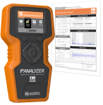
DVW Tool Box v.1.3 (13.4 MB) 04-11-2019
DVW Tool Box is an application-specific software tool for demonstration and evaluation of the CDM-VW300, CDM-VW305 and VWire 305 dynamic vibrating wire interfaces.
Device Configuration Utility v.2.35.02 (49.5 MB) 22-06-2026
A software utility used to download operating systems and set up Campbell Scientific hardware. Also will update PakBus Graph and the Network Planner if they have been installed previously by another Campbell Scientific software package.
Supported Operating Systems:
Windows 11 or 10 (Both 32 and 64 bit)
CR800 OS v.32.07 (4.41 MB) 15-05-2024
Execution of this download installs the CR800 Operating System and Compiler on your computer. It also updates the CR800 support files for the CRBasic Editor.
Note: This OS has crossed the 2 Meg CR800 size limit for remote download. The OS must be downloaded to the 2 Meg CR800 via direct connect with the Device Configuration Utility. All OS download methods are supported by the 4 Meg CR800.
Upgrading from versions prior to version 28 of the Operating System will reset the datalogger’s CPU drive. This is due to a change in the format of the file system from FAT16 to FAT32. In order for the datalogger to operate correctly, as part of the upgrade, the CPU drive is formatted to FAT32. Any programs stored and running from the CPU drive will be lost. It is not recommended to update the datalogger’s Operating System over a remote connection where program control regulates the communication equipment (turning it on or off, etc.). In these cases, an on-site visit and a backup using DevConfig’s backup utility is necessary to update the datalogger’s Operating System.
Watch the Video Tutorial: Sending an OS to a Local Datalogger.
In all cases where the datalogger is being updated from an Operating System prior to 28, the use of DevConfig’s backup utility is recommended due to the CPU drive being formatted using the new FAT32 format.
CR3000 OS v.32.07 (4.39 MB) 15-05-2024
Execution of this download installs the CR3000 Operating System and Compiler on your computer. It also updates the CR3000 support files for the CRBasic Editor.
Note: The Device Configuration Utility is used to upload the included operating system to the datalogger.
Upgrading from versions prior to version 28 of the Operating System will reset the datalogger’s CPU drive. This is due to a change in the format of the file system from FAT16 to FAT32. In order for the datalogger to operate correctly, as part of the upgrade, the CPU drive is formatted to FAT32. Any programs stored and running from the CPU drive will be lost. It is not recommended to update the datalogger’s Operating System over a remote connection where program control regulates the communication equipment (turning it on or off, etc.). In these cases, an on-site visit and a backup using DevConfig’s backup utility is necessary to update the datalogger’s Operating System.
Watch the Video Tutorial: Sending an OS to a Local Datalogger.
In all cases where the datalogger is being updated from an Operating System prior to 28, the use of DevConfig’s backup utility is recommended due to the CPU drive being formatted using the new FAT32 format.
常见问题解答
CDM-VW300: 8
展开全部收起全部
-
These devices work with vibrating wire strain gages, load cells, pressure transducers, crackmeters, and tiltmeters. Any standard, single-coil circuit vibrating wire sensor should work with these devices.
-
The CDM-VW300 offers two channels for simultaneous reading of two vibrating wire sensors, whereas the CDM-VW305 offers eight channels for simultaneous measurements. Other than the number of channels supported, both models operate identically.
-
Yes. When more than eight channels are needed in a system, multiple CDM-VW300-series devices can be connected to the same data logger.
- Each CDM-VW300 device provides two terminals.
- Each CDM-VW305 device provides eight terminals.
Any combination of CDM-VW300 and CDM-VW305 devices can be used to achieve the desired number of total terminals.
The list below, ordered by data logger and measurement rate, indicates the maximum number of supported terminals:
- CR3000, 100 Hz: 8 terminals
- CR3000, 50 Hz: 24 terminals
- CR3000, 20 Hz: 48 terminals
- CR1000, 100 Hz: not supported
- CR1000, 50 Hz: 8 terminals
- CR1000, 20 Hz: 32 terminals
- CR800-series, 100 Hz: not supported
- CR800-series, 50 Hz: 8 terminals
- CR800-series, 20 Hz: 32 terminals
-
The frequency outputs generated by the CDM-VW300 or CDM-VW305 can be scaled with known sensor response functions, which are provided by the manufacturer of the sensor. These frequency conversions are used to obtain measurement outputs expressed in the desired engineering units.
-
To communicate with CDM devices using the CPI protocol, the CR3000, CR1000, CR850, and CR800 dataloggers require an SC-CPI device. Only one SC-CPI device per data logger is required. It is expected that the design of future Campbell Scientific data logger products will work with CPI-based modules directly.
-
The communications protocol used by CDM devices is the CAN Peripheral Interface (CPI), which includes methods that are proprietary to Campbell Scientific.
-
Yes. Specific types of sensor measurements can be examined and evaluated before the system is deployed to a field site. A data logger is not used for this type of evaluation. Connect the CDM-VW300-series device directly to a computer using a USB cable. Using DVWTool software (specialized software included with the CDM-VW300 or CDM-VW305), the outputs of the attached vibrating wire sensors can be observed, and the CDM device can be configured appropriately.
-
CDM-VW300-series devices can measure vibrating wire sensors at the following rates: 1 Hz, 20Hz, 50Hz, 100Hz, 200Hz, and 333.3 Hz. CDM-VW300-series devices are designed for measurement periods of 1 s or less.