最多为4个229型土壤水分传感器提供激发电流。


概览
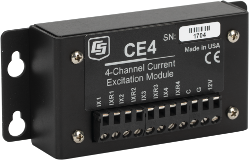
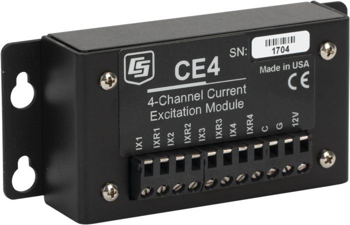
CE4是一种电流激发模块,该模块适用于恒定电流的加热元件,最多可同时支持4个229型热扩散水势传感器。使用229探头测量土壤水分水势时需要电流激发模块。
优势与特点
- Provides excitation current for up to four 229 sensors
- Allows up to four AM16/32-series multiplexers to be connected, which significantly expands the system's capacity
- Compatible with most Campbell Scientific data loggers
图像
3D/CAD 文件:
技术说明
CE4 电流激发模块可以向229的加热元件提供恒定电流,最多支持4个229。CE4 需要12V直流电源,数据采集器可以通过CE4 连接一个或最多4个AM16/32B扩展板,测量更多的229。
备注:CE4切换大于30mA的电流时,会降低扩展板继电器的可靠性,因此CE4使用过的扩展板不推荐再去连接其它的传感器。
产品规格
| Output | 50 mA ±0.25 mA (regulated) |
| Output Channels | 4 |
| Power | 12 Vdc source required |
| Active Current Drain | 25 mA + (50 mA) x (number of 229s connected to the CE4) |
| Dimensions | 11.5 x 5.4 x 2.7 cm (4.5 x 2.1 x 1.1 in.) |
| Weight | 131 g (4.6 oz) |
兼容性
Please note: The following shows notable compatibility information. It is not a comprehensive list of all compatible products.
数据采集器
| Product | Compatible | Note |
|---|---|---|
| 21X (retired) | ||
| CR10 (retired) | ||
| CR1000X (retired) | ||
| CR1000Xe | ||
| CR10X (retired) | ||
| CR200X (retired) | ||
| CR206X (retired) | ||
| CR211X (retired) | ||
| CR216X (retired) | ||
| CR23X (retired) | ||
| CR295X (retired) | ||
| CR300 (retired) | ||
| CR3000 (retired) | ||
| CR310 | ||
| CR350 | ||
| CR500 (retired) | ||
| CR5000 (retired) | ||
| CR510 (retired) | ||
| CR6 | ||
| CR800 (retired) | ||
| CR850 (retired) | ||
| CR9000 (retired) |
Additional Compatibility Information
Data Logger Considerations
The CABLE3CBL can be used to connect the CE4 to the data logger (see Ordering Info).
Power Considerations
The CE4 requires 12 Vdc power. A data logger control port is typically used to activate the module. When the control signal is received, all 4 channels output a 50 mA source current to the connected loads (typically 229 probes). When the control signal is dropped to 0 Vdc, output from the module ceases.
When active, the current required from the 12 V supply is approximately the following:
25 mA + (50 mA)(the number of 229 sensors connected to the CE4 outputs).
Multiplexers
The CE4 can source current for four probes directly. In applications that require more sensors, the output(s) of the CE4 can be connected to as many as four AM16/32B multiplexers, greatly expanding system capacity.
When using multiplexers, the user should be aware that switching currents of greater than 30 mA will degrade the contact surfaces of the mechanical relays. This will adversely affect the suitability of these relays to multiplex low voltage signals. Although a relay used in this manner no longer qualifies for low voltage measurements, it continues to be useful for switching currents in excess of 30 mA. Therefore the user is advised to record which multiplexer channels are used to multiplex the 50 mA excitation for the 229-L probes in order to avoid using those channels for low voltage measurements in future applications.
Enclosure Considerations
The CE4 requires a desiccated, non-condensing environment; a Campbell Scientific enclosure is recommended. The CE4's case has mounting flanges for attachment to the 1"-on-center hole grid of Campbell Scientific enclosures. Grommets and screws are provided to attach the flanges to the backplate of our enclosures.
常见问题解答
CE4: 7
展开全部收起全部
-
No. Typically a PRT will experience self-heating if more than 1 mA of current excitation is applied, while the CE4 or CE8 output is 50 mA.
-
The CE4 and CE8 are constant current devices designed to produce 50 mA of current on each channel. The voltage output will vary with the resistance of the connected load following Ohm’s law:
Vout = 0.05 A/RL where Vout is produced in volts and RL is the resistance of the load in ohms.
-
The CE4 and CE8 have CMOS circuitry controlled by a 0 to 5 Vdc analog signal provided by a data logger control port.
-
The CE4 and CE8 are constant current devices designed to produce a constant current to the 229-L Water Matric Potential Sensor. See the 229-L product page for more information.
-
While this could be done for a maximum resistance of 50 ohms in the ±2500 mV range and 100 ohms in the ±5000 mV range, it is not the best way to determine resistance. The preferred method for measuring an unknown resistance is to use data logger excitation channels. Current excitation channels can be used with a CR3000. Analog excitation channels with half-bridge or full-bridge circuitry can be used for other data loggers. See the specific data logger’s manual for further details
-
The active current drain can be calculated using the following equation:
Current drain = 25 mA + (50mA) x (number of 229-L sensors connected to the CE4 or CE8)For example, the current drain of a CE4 with 3 sensors is calculated like this:
Current drain = 25 mA + (50 mA) x (3 sensors) = 25 mA + 150 mA = 175 mA.- The current drain for a CE4 ranges from 75 mA to 225 mA.
- The current drain for a CE8 ranges from 75 mA to 425 mA.
-
Campbell Scientific recommends using the CABLE3CBL-L, a 22 AWG cable with three conductors and a drain wire. However, any type of copper wire between 18 AWG and 22 AWG could be used to control the CE4/CE8.